Technical support from 08:00 - 17:00 mon-fri
Free delivery on all orders exceeding £100
Next day delivery with selected 'priority shipping'
Technical support from 08:00 - 17:00 mon-fri
Free delivery on all orders exceeding £100
Next day delivery with selected 'priority shipping'
You’ve decided to buy a microphone or a headset with a built in microphone, and plugged it into your device, but it’s not working. What next?
In our experience, there are a multitude of reasons that it may not be working. Over the years, we’ve dealt with microphones and microphone systems alike, fashioned together from different pieces of equipment from various manufacturers, and it’s still one of the many issues that comes back to haunt us time and time again. The method of wiring used for the connection of the microphone or headset into your device is generally the culprit, but there may be other indications.
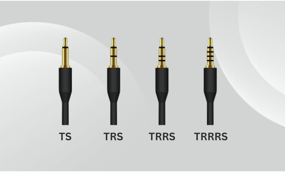
If this is your first time hearing TS, TRS, and TRRS, you may wondering what it all means. Simply put, these letters refer to different types of audio jack connectors; with each letter representing a distinct section of said connector. In essence, TS/TRS/TRRS all consist of either a Tip (T), Ring (R), or Sleeve (S). In regards to TRS and TRRS, both contain all three, respectively.
Upon further inspection of an Audio Jack connector, you’ll find either 2, 3, or 4 distinct sections. These comprise of Conductors, Rings, and a Sleeve. In layman’s terms, a conductor refers to the metal sections that carry electrical signals, whereas the rings refer to the black insulating bands that separate conductors. Last but not least, we have the sleeve, which refers to the longest section closest to the cable that is responsible for carriying the ground connection. Fundamentally, a ‘TS’ will contain 1 ring and 2 conductors, a ‘TRS’ will contain 2 rings and 3 conductors, and a ‘TRRS’ will contain 3 rings and 4 conductors.
As technology inevitably advanced, the need for an additional section became apparent, spurring on the development of TRS (3-pole) configurations. This included modifications to squeeze in a fourth connection.The same applied to TRRS (4-Pole), with an additional section created for microphone use too.
We’ll provide an image of the comparisons below to give you a better idea of how these connectors are constructed.
As with the majority of audio jack connectors, they all have their distinct uses.
Additionally, there is a further connector that we haven’t yet delved into, due to it’s rarity. This is called TRRRS.
Unlike the previous three, TRRRS is specialised, and has been exclusively designed for other uses, namely in the gaming industry to support stereo audio and microphone functionality for ‘Astro Gaming’ headsets.
2.5mm (Subminiature)
The 2.5mm audio jack is a subminiature connector that is available in both 3-pole stereo and 2-pole mono configurations. It became increasingly popular amid the rise of portable electronics, particularly throughout the 90’s and early 2000’s for mobile phone use. Most common applications include audio in antiquated mobile phones, two-way radios, MP3 players, and a handful of gaming headsets.
3.5mm (Mini-Jack)
The 3.5mm audio jack, also known as the ‘mini-jack’ was adopted as the universal standard for personal and portable audio due to it’s compact size, durability, and ability to deliver superb stereo sound via a TRS connector. Developed as a smaller alternative to the 6.35mm audio jack, the most notable uses include compact electronics spanning 70+ plus years, such as transistor radios in the 50’s and 60’s, and later soldified by the Sony Walkman in 1979.
4.4mm (Bantam/Pentaconn)
The 4.4mm audio jack is a 3-pole TRS connector used primarily in professional audio, and otherwise known as Bantam.This specific type of audio jack may also be referred to as a ‘Tiny Telephone (TT) plug‘, hence it’s use in Tiny Telephone patch panels. Modernised equivalents include Pentaconn’s 5-pole TRRRS configuration developed by Nippon DICS in 2015, to provide balanced headphone audio using the same 4.4mm form factor.
6.35mm (1/4″)
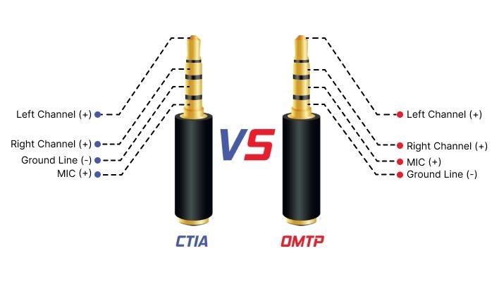
Despite this, two microphone standards prevailed, and those were officially named OMTP and CTIA — the former initially implemented on older devices, and CTIA on the more modern devices. So, what’s the difference?
As you can see on the image included below, both the CTIA and OMTP standards use the tip of the connector for the left loudspeaker connection, with the first ring connection being used for the right loudspeaker connection. Then, they change places! The OMTP standard houses the second ring connection for the microphone signal, using the final sleeve connection as a common ground. The CTIA method, swapped these around and used the second ring for the common ground, and the sleeve connection for the microphone signal. Long story short, CTIA came out on top.
This slight difference is all that’s needed to cause problems for both your headset and microphone. Sometimes, if you’re lucky, it just won’t work. Whereas, with other scenarios you may find the microphone works, but the volume is either low or distorted. This could be attributed to volume issues with the headphones, and in turn, cause you to experience stereo reproduction from both ears of your headset.
Ideally, the manufacturers of both the device and the peripheral would inform you of how the product is wired, but with a lot of imports hitting the market, this can rapidly become an impossible task. There are even some large modern manufacturers that use the same connector for control of their devices and employ proprietary wiring to the same TRRS connector, which leads to a whole new set of problems.
It may sound all doom and gloom, but fortunately, we can provide a number of solutions (mostly through trial and error). Still, you can’t beat the experience and knowledge of an expert to steer you in the right direction.
So, what benefits does the CTIA method of wiring provide?
OMTP still has it’s uses, albeit limited. Some of the associated benefits include:
Overall, the OMTP standard of TRRS wiring found major success upon implementation in 2007-2008, and continued to be adopted across myriad devices, namely smartphones, up until 2010-2011.
Shortly after, a more advanced standard was introduced; that being CTIA. From then on, the vast majority of major manufacturers outside of China began switching to the CTIA (Cellular Telecommunications and Internet Association) standard. This is also known as AHJ — American Headset Jack, and is still the de facto TRRS standard for most modern devices in North America.
We’ve previously outlined the versatility of USB Mics in a previous blog post, so we’ll focus on their features and applications this time. First and foremost, a USB Connector, otherwise known as Universal Serial Bus, is a plug-and-port system used to connect devices, such as phones, mice, flash drives, printers, microphones, and even external hard drives to a computer (or to each other). USB’s effectively function as plug-and-play interfaces, allowing peripheral devices to be connected, recognised, and immediately used without manual configuration or system resets.
Relatedly, this is where USB ‘hot swapping’ comes into play, allowing peripherals to be connected and/or disconnected without powering down your computer. This foundational feature gives you a higher degree of functionality, whilst at the same time, preventing system shutdowns. With that being said, it is generally considered best practice to safely remove any storage devices after use to prevent data corruption.
In practice, a USB connector will predominantly handle three jobs…
1: To transfer data. This lets devices send and receive information, including files, audio, video, and other commands.
2: To supply power. Capable of charging devices or powering them directly (for instance, a webcam or keyboard).
3: To allow communication between devices. Informs the computer what is connected and how to use it (plug-and-play).
A standard USB system contains five primary connection types, and offer a wide range of benefits and uses. We’ll aim to provide a brief, chronological synopsis on each connection type below.
DIN (Deutsches Institut für Normung)
Fundamentally, a DIN connector is a type of electrical connector, named after the German standards body ‘Deutsches Institut für Normung’, from which it derives the name. This connector is widely known for its circular shape with pins arranged in a circular pattern, used for various audio, video, data, and power connections. Most famously in older style keyboards, MIDI, and even S-Video. The DIN connector also contains several different pin counts and arrangements, such as the 5-pin, 6-pin, or the standard 3 to 8 pins.
The most ubiquitous variation of the DIN connectors used today is the 5-pin DIN, with the majorty of uses coming by way of MIDI (Musical Instrument Digital Interface). Introduced in 1983 to allow synthesisers, drum machines, keyboards, and computers to communicate, MIDI was designed to use a specific type of DIN connector to standardise connections between electronic musical instruments. To this day, it’s still the standard for professional music audio, despite USB’s also being able to carry MIDI signals.
There are many reasons as to why the commonplace 5-pin DIN connector was overwhelmingly used for MIDI. These include:
XLR (eXternal Line Return)
The XLR connector was able to solve a plethora of issues that other connectors simply couldn’t, particularly in demanding acoustic environments. Whether that be professional audio, lighting, or broadcast applications.
In terms of deciding a ‘winner’ between DIN or XLR. Well… it really does boil down to your intended application. Each connector serves a distinct purpose. But, for the vast majority of AV applications that require both, XLR is likely the way to go.
To summarise, DIN connectors are frequently used in legacy equipment or applications requiring unbalanced analog signals. Whereas with XLR connectors, you’re going to notice significantly better metrics when used in professional & live audio, due to their effectiveness over long-distances.
Technology is continually advancing, and it’s now easier than ever to get left behind with more sophisticated products hitting the shelves every so often. Fortunately, for anyone dabbling in the AV world, or simply wanting to learn more about the inner workings. applications (and uses) of microphone connectors, we’re here to make things a little bit easier.